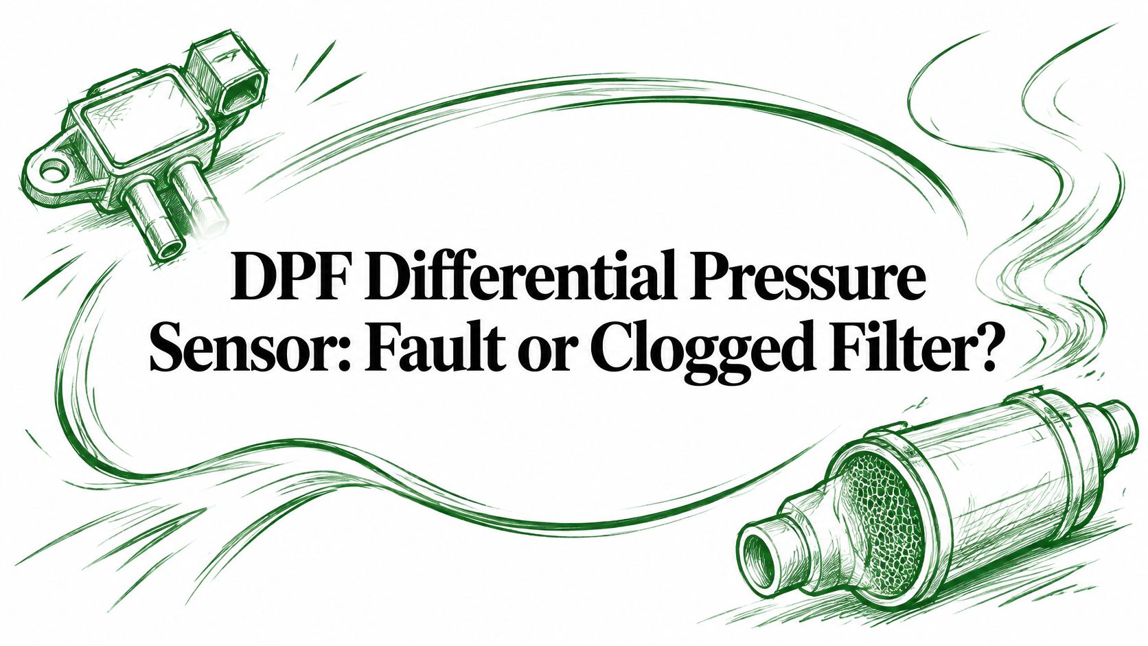
Ask a driver what a high DPF differential pressure reading means and the answer comes back fast: the filter is clogged and it has to come off. That answer is right just often enough to cost real money. The number on the scan tool doesn't come from the filter. It comes from two take-off ports, two narrow tubes, a sensor body and a wiring connector, and any one of those parts can lie convincingly.
The expensive version of that lie is a filter that gets removed, baked or replaced while the actual fault, a split hose, a water trap or a corroded terminal, stays on the truck. The warning returns a few hundred miles later, the second repair gets blamed on the first, and the downtime doubles. A pressure code is a claim to test, not proof of a loaded filter.
What follows is the order that separates the two: what the sensor measures, which patterns point at the measurement path and which point at soot, what to record before anyone touches the truck, how to inspect the tubes, which circuit values to compare, when a high number means restriction, and the gates worth clearing before a filter replacement gets authorized.
Table of Contents
- What a DPF Pressure Sensor Measures and Why It Matters
- Telling a Sensor Fault From a Clogged Filter
- Symptoms and Records to Gather Before Testing
- How to Inspect the Pressure Tubes and Sensor Mounting
- Live Readings and Circuit Values to Compare
- When a High Reading Points to a Real Restriction
- Confirm the Sensor Before Authorizing DPF Replacement
What a DPF Pressure Sensor Measures and Why It Matters
On a system with two pressure lines, one connects upstream of the diesel particulate filter (DPF) and the other downstream. The sensor measures the difference between those two pressures and sends a signal to the engine control unit. Use the service information for the installed engine to identify the ports and how the signal should behave.
At comparable exhaust flow and temperature, a clean filter generally has a smaller pressure drop. Soot or ash can increase that drop by restricting flow. The control unit can use pressure data alongside other inputs to estimate soot loading and help determine when regeneration is needed.
On that design, the measurement path includes both take-off ports, both tubes, the sensor and its wiring. A fault anywhere along that path can distort the reading even when the filter itself is serviceable.
Why the reading is a signal and not a verdict
Restriction is only one influence on the value. Exhaust mass flow, gas temperature, ash that never burns off, the condition of the sensor lines and the engine's operating state all push it around. An SAE technical paper on sensor-based particulate filter diagnostics (2013-01-1515) makes the point directly: those disturbance variables are what make differential-pressure monitoring increasingly difficult to interpret against strict onboard diagnostic requirements.
A single high differential-pressure value should never be read as a failed or fully loaded filter. It should be read as a question about the whole measuring path.
Start by checking the full measurement path. A qualified technician can compare the key-on, engine-off reading with the expected offset and check how pressure responds under the operating conditions specified by the manufacturer. If the procedure calls for testing under load or checking pressure after regeneration, confirm that the unit, site and equipment allow the test safely.
If pressure stays implausibly high, flat or erratic, the sensor and its plumbing get tested before a filter is condemned. Incorrect sensor data drives unnecessary aftertreatment work, and that work drives derate-related downtime while the truck sits.
Telling a Sensor Fault From a Clogged Filter
A high reading can come from restriction or a fault in the measuring system. Inspect the pressure tubes, mounting, connector and wiring before drawing a conclusion. In Cummins bulletin TSB220250, issued in 2022, moisture in the sensor is identified as a cause of misleading fault codes on specified X12 and X15 engines. Check applicability against the engine and the recorded fault codes.
Use the table to choose the next check. Several faults can produce the same reading, and a sensor or tube fault can coexist with a restriction.
| Pattern observed | Likely cause | First check |
|---|---|---|
| High pressure, steady readings, returns soon after regeneration | Possible soot or ash restriction | Verify the measurement path and compare with OEM data under specified conditions |
| High or flat readings after rain, washing or bracket work | Moisture in tubes or incorrect sensor orientation | Inspect tube slope, orientation and standing moisture |
| Flat, erratic or implausibly low pressure | Blocked, kinked or leaking tubes, or sensor fault | Inspect both lines for plugging, kinks, leaks and loose fittings |
| Signal outside the OEM range with ignition on | Wiring, connector or sensor circuit | Check connector condition, reference voltage and ground |
| Pressure changes but signal stays flat | Sensor fault | Use the OEM pressure test and compare the electrical response with the specified signal curve |
| Reading returns to normal after tube correction | Installation or routing fault | Retest live data before any DPF replacement |
How to read the table without talking yourself into a filter
A steady high reading can justify checking for a restriction after the measurement path passes its tests. If correcting a tube brings the reading back within specification, repeat the check under the conditions that triggered the fault before approving any filter work.
Practical rule: two tubes, a sensor and a connector are cheaper to inspect than a filter is to remove. Prove the path first, then judge the filter.
There's a trap in this work worth naming. Replacing the sensor alone often fails to cure a recurring fault, because the reason the sensor failed, moisture collecting in a low spot of the tube or a bracket that was reinstalled in the wrong orientation, is still on the truck. The replacement reads correctly for a few weeks and then the same code returns. Ownership of the fix belongs to whoever corrects the routing, not whoever swaps the part.
Symptoms and Records to Gather Before Testing
A complete intake record helps the technician choose the first checks and spot a recurring fault. Dispatch can gather the dash message, operating conditions and location before the visit. Leave scan-tool readings and component inspection to qualified personnel where access is safe.
Fault codes exactly as displayed. Active and stored codes written down character for character, plus any freeze-frame data the scan tool shows. Paraphrased codes send the diagnosis down the wrong path.
Warning and derate messages. The exact text of any dash message, reduced-power notice or countdown, and whether the truck derated or only warned.
Engine speed and load at first appearance. Whether the truck was loaded, climbing a grade, idling in traffic or cruising, because exhaust flow at that moment changes what the reading should have been.
Where it happened in the drive cycle. A warning that appears at key-on tells a different story from one that appears forty minutes into a loaded run.
Regeneration history. Whether a regeneration was attempted, completed or interrupted, and what the pressure reading did afterward.
Exposure events. Rain, pressure washing, recent exhaust or sensor work, harness or bracket disturbance, and any component replaced in the last few weeks.
Photographs of tube routing and the sensor mount. Share existing photographs or take new ones only when the components are visible from a safe position. Leave any inspection beneath the truck to the technician.
Conditions at the time. Date, time of day, ambient temperature and whether the warning returns after the key is cycled.
Use the timing to guide the next check. A fault under load warrants comparing pressure and circuit behavior as conditions change. A fault after a wash warrants checking for moisture. Either pattern can have more than one cause.
If a warning has already come back once after a regeneration, the fields in what to document when a DPF warning returns after regeneration are worth completing in full before the next visit. The intake sheet travels with the truck, so the technician starts from evidence instead of from a code alone.
How to Inspect the Pressure Tubes and Sensor Mounting
A qualified technician should inspect the lines only after the exhaust has cooled and the vehicle has been secured against movement. If the work requires access beneath the truck, use a controlled work area and the support equipment required by the manufacturer.
Cummins bulletin TSB140105, updated in 2014, describes how moisture trapped by incorrect sensor orientation can distort readings. It recommends a downward tube angle of about 10 degrees for the installations it covers. Use the routing, angle and mounting requirements for the engine and aftertreatment system being serviced.
Inspection sequence that settles the question
Let the exhaust cool and secure the vehicle. Follow the manufacturer's safety procedure before opening a pressure line or working beneath the unit.
Check sensor orientation and tube slope. Compare the installation against the service information for the unit and look for low spots where moisture can collect.
Inspect each tube along its full length. Look for plugging at the take-off union, kinks, cracks, chafing, heat damage, loose fittings and standing water or soot condensate. A tube restricted on the downstream side distorts the difference just as badly as one blocked upstream.
Confirm each tube reaches the correct port. A crossed high-side and low-side connection inverts the reading, and it happens most often after earlier exhaust work.
Look for moisture traces after exposure events. Rain, washing and disturbed brackets are the usual triggers, and dried staining near a fitting is the tell.
Correct faults and retest. Use the specified parts and routing. Record the key-on, engine-off offset and compare it with the manufacturer's specification.
Review live data before approving further work. Follow the OEM diagnostic path for the fault codes and the verified readings.
Roadside access, the tools on the truck and the physical position of the tubes decide how much of this gets done at the vehicle location. Tubes routed tight against the frame or behind a heat shield may need equipment or access that isn't realistic on a shoulder, and that assessment comes before any work starts.
Live Readings and Circuit Values to Compare
Use the wiring diagram and test procedure for the engine and aftertreatment system. Identify the circuit type, pinout and expected values before testing. On an analog circuit, verify the supply and ground, then compare the signal with the manufacturer's specifications at the prescribed pressure and operating condition.
Inspect the connector and harness first. Melting, cracking, corrosion, water ingress and loose or spread terminals account for a large share of bad signals, and they cost nothing to find.
Verify supply voltage and ground. Use the manufacturer's specified test points and ignition state.
Check the signal during the specified test. Compare its response with the OEM curve over the required pressure range.
Compare the signal with independent pressure measurements when the OEM procedure calls for it. Use the specified equipment and connection method. If the readings disagree, investigate the tubes, wiring and sensor before assigning the fault to the filter.
What the approximate numbers are good for
Generic pressure and voltage examples can illustrate how a sensor responds. For a diagnostic decision, record the values in the service information for the exact configuration. Use the specified pressure units, measurement location, engine state and equipment.
| Check | What to record | Where to verify it |
|---|---|---|
| Sensor supply and ground | Voltage and ground readings under the prescribed test conditions | OEM wiring diagram and circuit test |
| Sensor signal | Response at the specified test pressures | OEM signal specification for the installed sensor |
| Key-on, engine-off plausibility | Pressure offset before the engine starts | OEM diagnostic procedure |
| Pressure under specified operating conditions | Measured pressure, engine speed, load and temperature as applicable | OEM pressure limits and test conditions |
| Pressure test equipment | Instrument range, connection points and measurement units | OEM tool and procedure requirements |
Set up any pressure test in a controlled area according to the service procedure. Let the exhaust cool before opening lines or making connections. Use the required equipment and keep clear of hot exhaust and potential discharge. Perform running or loaded tests only when the procedure and vehicle condition permit them.
When a High Reading Points to a Real Restriction
Use the manufacturer's restriction test for the installed engine and filter. Ford's 2023 diesel OBD summary illustrates why the fault code matters: P244A monitors pressure that falls below a flow-dependent threshold for the missing-substrate check. A suspected restriction calls for the applicable high-restriction diagnostic procedure.
| Condition | What to establish | Where to verify it |
|---|---|---|
| High reading at a comparable operating point | Confirm the sensor, lines and signal first | OEM sensor and pressure test procedure |
| Verified pressure above the applicable limit | Confirm a restriction and assess the cause before selecting service | OEM restriction and filter service procedures |
| Pressure remains high after an eligible regeneration | Check for residual restriction, ash loading or another cause | OEM post-regeneration evaluation |
The EPA bulletin on retrofit DPF operation and maintenance explains that soot or ash can impede flow and increase exhaust backpressure. Follow the manufacturer’s limits for the installed system. Regeneration addresses soot, and ash requires an appropriate cleaning process.
Actual restriction from soot, ash or another cause. Confirm that the pressure measurement is valid and exceeds the OEM limit under the specified conditions.
A misleading reading. A plugged or leaking line, trapped moisture, wiring fault or drifting sensor can make the reported value inconsistent with independent pressure measurements.
Normal variation from engine speed, exhaust flow, temperature, altitude and the filter's own design, where the number is what that engine does at that flow.
Clearing codes or starting a regeneration on the strength of one snapshot is how a truck ends up with a fresh filter and the same fault. Pressure and time together tell the story.
A qualified technician may perform a commanded regeneration at a suitable location when the OEM procedure permits it for the active warnings, fault codes and filter condition. A stationary regeneration needs a secured unit, an approved tool and a clear, ventilated area with the clearances the manufacturer requires. Keep the vehicle out of service if the manufacturer calls for shutdown or movement is unsafe. Follow the manufacturer’s instructions for any active warning or lockout. The Cummins parked-regeneration guide describes exhaust-area precautions for covered systems. Filter removal or off-vehicle cleaning may require transport to a suitable external facility.
Confirm the Sensor Before Authorizing DPF Replacement
Use these three checks to decide whether the problem is in the measurement path or whether a filter service decision is justified.
Check the pressure lines. Verify the correct ports and the routing specified for that installation. Repair any tube fault and repeat the test.
Check the sensor circuit. Verify power, ground and signal, then perform the OEM pressure comparison if specified.
Check for a real restriction. Once the measurement path is verified, compare valid pressure measurements with the OEM thresholds under the specified operating conditions. Review regeneration history and any evidence of soot, ash or filter damage.
If the signal stays flat, erratic or otherwise implausible, continue testing the measurement path. Authorize filter cleaning or replacement only when the OEM diagnostic procedure confirms a filter condition that calls for it. For example, Cummins TSB220250 calls for a soot-load reset and stationary regeneration after sensor replacement on the covered engines with specified fault combinations. Follow the applicable service procedure for the exact unit before resetting a value or commanding a regeneration.
SAAT Repairs Corp provides mobile diagnostics and DPF and EGR service at the vehicle’s location when access and job requirements allow. The technician determines which work can be completed on site and when a suitable external facility is needed. Arrival estimates depend on location, traffic, technician availability and the job.
Have the intake sheet from the records section ready before the call, including the code text, the load conditions and photographs of the tube routing. A filter replacement is one of the more expensive decisions in aftertreatment work, and the DPF cleaning cost breakdown is worth reading before approving one on the strength of a single pressure value.
SAAT Repairs Corp provides mobile Road Services in Tampa, Lakeland and nearby areas. Share the unit location, engine information, fault codes and the conditions when the warning appeared. The team can assess what the truck needs and where the work can safely take place.