A semi-truck electrical problem that shows 12.6 V at rest but drops below about 13 V while running often points to voltage integrity, ground resistance, or network communication trouble rather than a single failed sensor or module. A truck may start after a jump, travel a short distance, and then display several unrelated warnings because one unstable circuit is affecting multiple electronically controlled systems.
That situation is familiar along the Tampa and Lakeland corridors. The driver reports a dead battery, a flickering dash, or a no-start condition. The dispatcher hears “electrical problem,” while the truck's control modules may be reporting the consequences of a damaged harness, poor ground, charging fault, or interrupted data connection. Good semi-truck electrical repair starts by separating those fault families before anyone replaces parts.
Table of Contents
- When a Semi Truck Acts Up - What to Look for Before Dispatch
- Wiring, Power, and Module Faults Explained
- How to Diagnose Semi Truck Electrical Problems at the Vehicle
- ECU Tuning, Programming, and Calibration - What Separates Them
- When Semi Truck Electrical Repair Needs an External Facility
- What Fleet Managers and Operators Should Document Before and After Repair
When a Semi Truck Acts Up - What to Look for Before Dispatch
A common roadside sequence begins with a jump-start. The engine fires, the truck leaves the shoulder, and several miles later the dash fills with warning lamps. The driver may assume the batteries are weak again. That conclusion is possible, but it isn't sufficient. A high-resistance cable, failed ground, unstable alternator output, or communication fault can make healthy components appear defective.
Modern diagnosis changed because commercial engines changed. The National Highway Traffic Safety Administration's technical record reports that electronic controls became standard on all heavy-duty engines between 1991 and 1994, while medium-duty engines reached that standard in 1998. Electronic fault isolation now involves sensors, wiring, control modules, fuel-injection controls, and data circuits, not only mechanical inspection.

Capture the symptom before resetting anything
The first useful report is specific and time-stamped by the event, not by guesswork. Before disconnecting batteries or clearing codes, the driver or fleet contact should record:
- Battery condition: Note engine-off voltage, whether the truck needed a jump, and whether the starter clicked, turned slowly, or cranked normally.
- Warning behavior: List active warning lamps, flickering displays, messages, and whether several systems failed together.
- Operating result: Record whether the truck derated, shut down, lost gear selection, or continued running with reduced performance.
- Physical clues: Photograph corrosion, loose lugs, damaged insulation, wet connectors, rubbed harnesses, and heat-discolored terminals.
- Recent history: Document battery, alternator, starter, wiring, or module work and any repeated fuse failures.
A report such as “dead battery again” hides the decision that matters. A report such as “the engine started after a jump, the dash flickered under load, several warnings appeared, and the truck later derated” gives a mobile technician a meaningful starting point.
Practical rule: A jump-start proves that the starter received enough energy once. It doesn't prove that the batteries can deliver cranking current repeatedly, that the alternator is charging, or that the ground path can carry load.
The fleet breakdown response checklist can help dispatchers preserve the information needed before requesting mobile Road Services. At the vehicle, the technician can then assess whether testing and repair are safe with the available access, lighting, equipment, and traffic protection.
Treat several codes as a pattern
Multiple fault codes don't automatically mean multiple failed components. A low-voltage event can disturb sensors and controllers at the same time. A damaged data harness can interrupt communication with an engine controller, transmission controller, or other electronically coordinated system.
The useful question is not “Which module should be replaced?” It is “What common power, ground, harness, or communication path could explain the pattern?” That shift prevents a parts-replacement cycle and helps determine whether the truck can return to service after a roadside repair or needs controlled access at an external facility.
Wiring, Power, and Module Faults Explained
Three fault families shape most commercial electrical diagnosis: wiring faults, power-supply faults, and communication failures. Similar symptoms can arise from any of them, so each family requires its own test sequence and repair boundary. This decision framework helps determine whether a roadside repair is reasonable or whether the truck needs controlled access elsewhere.
Wiring faults create intermittent behavior
A wiring-harness fault may involve chafed insulation, broken conductor strands, corrosion inside a connector, water intrusion, or a terminal that loses tension under vibration. The truck can run normally in the yard, then fail after the harness shifts, the engine vibrates, or a high-current accessory is switched on.
Harness damage has been documented in several exposed areas. An NHTSA investigation into heavy-truck wiring identified rubbing near an air-compressor support bracket, transmission case, and coolant surge tank. Damage in those locations can lead to intermittent codes, warning messages, erratic operation, no-start conditions, derates, shutdowns, or loss of transmission gear selection.
A continuity test may show a path even when the conductor cannot carry operating current. Voltage-drop testing under load, connector inspection, and a controlled wiggle test provide better evidence than an unloaded meter check. An accessible connector or damaged wire may be repairable at the vehicle when safe access exists. Full harness replacement, difficult routing, and damage inside a protected assembly usually call for an external facility.
Power faults starve otherwise sound electronics
Power faults include weak batteries, corroded terminals, high-resistance positive cables, poor engine grounds, alternator faults, and regulator or control problems. They can cause slow cranking, flickering displays, repeated sensor codes, communication loss, and apparent module failure.
The distinction is measurable:
| Fault area | Useful observation | What the result suggests |
|---|---|---|
| Battery at rest | Approximately 12.6 V for a fully charged typical 12-volt battery, according to heavy-duty charging-system guidance | A resting reading alone does not prove cranking capacity |
| Charging voltage | Generally about 13.5 to 14.5 V while running | Below approximately 13 V suggests undercharging, while excessive voltage points toward regulator or control trouble |
| Cranking voltage drop | More than 0.2 V across the positive cable or engine-ground path indicates excessive resistance | Corrosion, loose terminals, damaged strands, or poor bonding deserves inspection |
Replacing the battery repeatedly can hide the actual fault. An alternator, regulator, parasitic circuit, or bad ground can discharge or damage a replacement battery just as it affected the previous one. Confirm the charging and ground paths before authorizing another battery.
Communication faults spread across systems
J1939 networks use CAN communications, shielded twisted-pair wiring, and commonly a 250-kbit/s data rate. The network typically uses 120-ohm termination resistors at both ends of the backbone. With power removed, approximately 60 ohms across the complete network provides a useful first integrity check, as described in J1939 diagnostic guidance.
Substantially higher resistance can indicate an open circuit or missing termination. Substantially lower resistance can indicate a short or extra termination. Isolate the inactive branch or module, then verify its power and ground before condemning an ECU. That sequence separates a network problem from a failed controller.
For a focused example of why wiring should be tested before parts are changed, review these PACCAR MX-13 injector wiring checks. A sensor code identifies a reported condition. Physical inspection and circuit testing identify the failed section.
How to Diagnose Semi Truck Electrical Problems at the Vehicle
A truck that cranks slowly at a rest area, loses dashboard power, or logs several communication faults needs a sequence, not a parts guess. Start by establishing the electrical baseline, apply a controlled load, then isolate the circuit that loses voltage or communication. A scan code identifies a reported condition. Circuit testing identifies where the fault sits.
Establish the electrical baseline
Secure the vehicle for the operating conditions. Stop testing if access exposes personnel to traffic, moving equipment, hot components, or unsafe electrical energy. With safe access available, record these checks:
- Measure engine-off battery voltage. Capture the reading before charging or jump-starting changes the evidence. Test batteries individually under load when equipment and access allow.
- Observe cranking behavior. A slow starter, clicking solenoid, and normal crank point toward different areas. Compare voltage at the battery posts with voltage at the starter feed instead of relying on the dash display.
- Measure alternator output at the battery. Run the engine with electrical accessories operating. A normal reading at the alternator can still conceal resistance in the cable or ground path.
- Test positive and ground voltage drop under load. Check both paths during cranking and record where the voltage is lost. The charging-circuit test reference provides a practical reference for interpreting these measurements.
- Inspect and flex accessible harness sections. Look for rubbed insulation, loose clamps, moisture, damaged connectors, and changes in voltage or communication while moving the harness carefully.
Use a load test to evaluate cable and connection resistance. If the charging path fails under load, inspect the positive cable, grounds, terminals, and connections before replacing the alternator. A separate ripple test helps identify diode failure. Load performance and ripple behavior answer different questions, so one test cannot replace the other.
Decide what belongs at the vehicle
The mobile decision depends on access, safety, and fault location.
| On-site assessment may be reasonable | External facility may be necessary |
|---|---|
| Battery, starter, alternator, cable, and ground testing | Harness replacement requiring extensive disassembly |
| Accessible connector, terminal, or wiring repair | Reflashing that needs stable controlled power and manufacturer-level access |
| Fault-code capture and module power checks | Damage inside protected assemblies or difficult-to-access routing |
| Low-voltage communication checks | Aftertreatment or calibration work requiring controlled verification |
| Lighting or starting-system diagnosis | Work that cannot be performed safely on the shoulder or at the vehicle location |
Record the fault codes, measured voltages, test conditions, and harness areas inspected. The Cascadia DD15 electrical diagnostics guide reinforces the proper order: verify power, ground, wiring, and communication before programming or module replacement. A mobile Road Services technician can define the repair scope at the truck, while extensive routing work, protected assembly damage, and controlled software procedures may require a facility.
ECU Tuning, Programming, and Calibration - What Separates Them
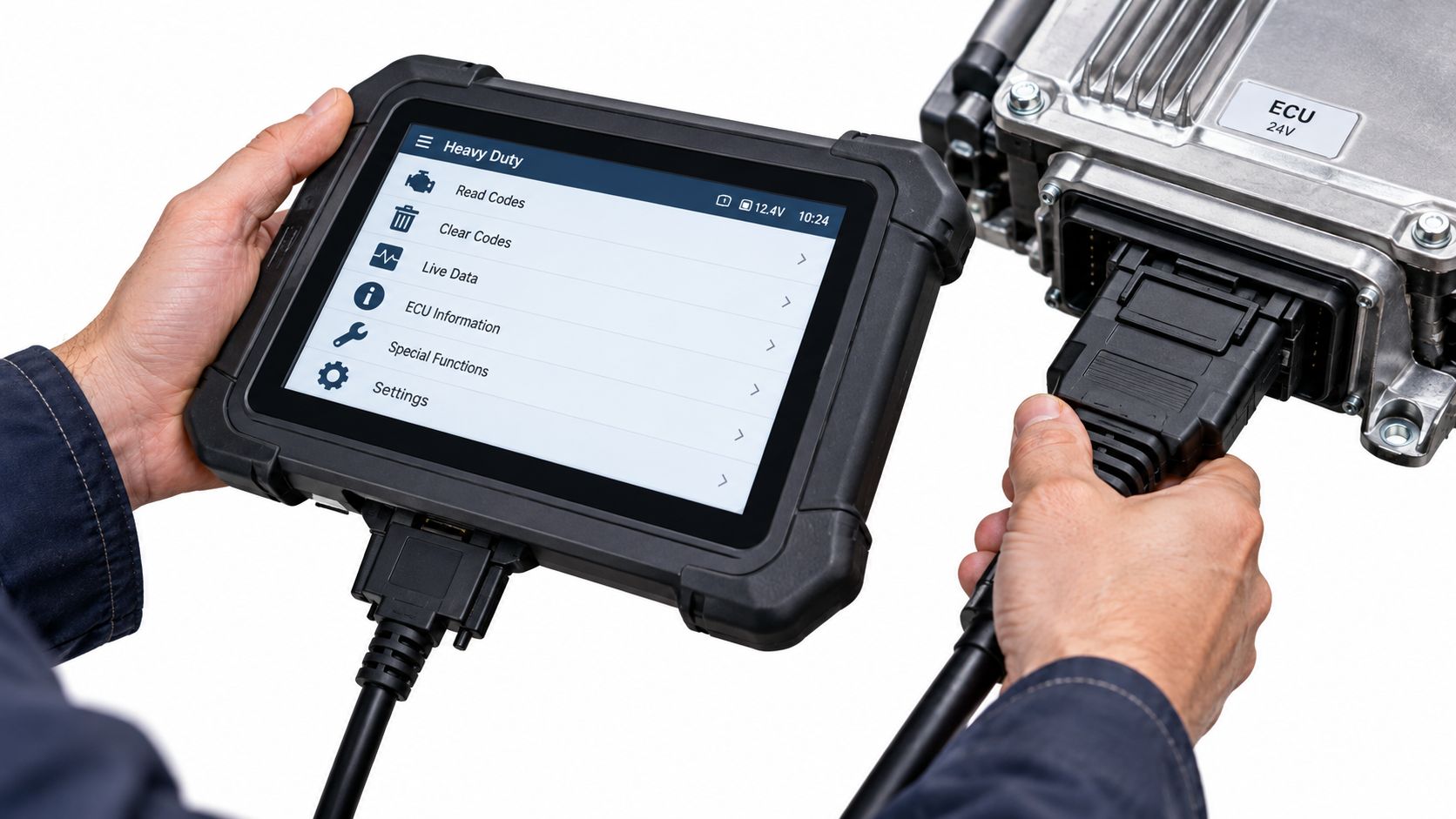
A truck arrives with reduced power, a warning light, or a no-start complaint. The technician connects a scan tool, but the tool alone does not identify the job. Tuning, programming, and calibration affect different parts of vehicle operation and carry different risks.
Tuning changes operating behavior
ECU tuning changes performance parameters. Depending on the platform and calibration, it can affect fuel control, torque behavior, turbo response, or shift strategy. Tuning changes performance parameters rather than repairing damaged power feeds or restoring communication.
It also raises questions about emissions compliance, warranty conditions, operating policy, and regulatory exposure. A truck that needs electrical diagnosis should not become a tuning candidate just because the engine has reduced power. Reduced power can come from an unresolved sensor, harness, voltage, or aftertreatment fault.
Programming restores controller software
Programming writes or refreshes controller software, aligns a replacement module with the vehicle configuration, or applies a compatible update. It may be appropriate after wiring integrity has been proven and a controller requires software work.
The historical development of electronic control shows why this distinction matters. The Detroit Diesel Series 60 history records production from 1987 through 2011, with DDEC-III widely installed during the first half of the 1990s, DDEC-IV introduced in 1996, and DDEC-V appearing in 2002 with a dual-control architecture using two microprocessors. The same history connects those generations with progressively stricter EPA 1994, 1998, 2004, and 2007 emissions standards.
These systems coordinate more than basic engine operation. Programming with unstable voltage or an unresolved network fault can interrupt the process or leave the original fault untouched. Before software work, preserve active and inactive codes, verify power and grounds, protect module voltage, and confirm the correct vehicle configuration.
The following video provides general visual context for electronic control-system testing. It does not replace vehicle manufacturer service information or a site-specific diagnosis.
Calibration teaches the repaired system
Calibration or relearn procedures allow a controller to apply known settings after a repair. Depending on the vehicle and repair, the procedure may address idle behavior, transmission adaptation, sensor alignment, or aftertreatment parameters.
The practical rule is simple:
| Operation | Primary purpose | Electrical diagnosis still required |
|---|---|---|
| ECU tuning | Changes vehicle behavior or performance parameters | Yes, because tuning does not repair unstable power or wiring |
| Software programming | Restores or updates controller software | Yes, before and during the programming event |
| Calibration or relearn | Applies required post-repair settings | Yes, to confirm the underlying circuit is stable |
Clearing codes does not perform any of these operations. A reset may remove a symptom briefly while the voltage or communication failure remains. The repair decision should therefore start with the fault type and circuit condition, then determine whether software work is appropriate.
When Semi Truck Electrical Repair Needs an External Facility
Mobile Road Services are valuable when the truck can be safely accessed and the fault is within the equipment and conditions available at the vehicle. The roadside isn't automatically the right place for extensive harness removal, protected-module access, or software work that needs stable controlled power.
Environmental conditions can decide the boundary. Traffic exposure, poor lighting, limited clearance, weather, damaged bodywork, or a harness routed through inaccessible areas may make a technically simple repair unsafe at the truck. A suitable external facility may then be the responsible option, even when the original complaint began with a battery or warning light.
High-voltage systems require a separate safety decision
Conventional 12- or 24-volt circuits aren't the same as exposed high-voltage equipment. Federal Motor Carrier Safety Administration training material warns personnel not to touch exposed metal inside high-voltage cabinets, enclosures, conduits, or components. It also warns against piercing, prying, dismantling, or forcing open labeled barriers and against cutting orange-colored cables, as stated in the FMCSA high-voltage safety material.
That guidance changes the dispatch conversation. Battery, starter, alternator, ground, accessible wiring, and low-voltage diagnostic work may be considered after the vehicle is secured. Exposed high-voltage systems require appropriate isolation procedures, specialized competence, and potentially an external facility.
Protect the repair from repeating
A truck that has already received a battery or module but continues to fail needs root-cause review. The technician should preserve codes before disconnection, verify the original symptom, inspect the harness and grounds, and document measured voltage rather than relying on a cleared dash.
This matters for emissions-related faults as well as drivability. Electronic controls regulate fuel pressurization, injection, and timing, so a power or sensor problem can affect engine output, emissions performance, and derate behavior while the engine still runs. A roadside reset without circuit repair can send the truck back into service with the same failure waiting for vibration, heat, or electrical load to expose it again.
The proper outcome isn't always a completed roadside repair. Sometimes it is an accurate diagnosis, safe stabilization, clear documentation, and an external repair recommendation that prevents unsafe improvisation.
What Fleet Managers and Operators Should Document Before and After Repair
Repair records should show the fault, the test, and the result. Before dispatch, capture active and inactive codes, engine-off and running voltage, warning-lamp behavior, recent battery or alternator work, visible corrosion, damaged insulation, and the circumstances of the failure.
After the visit, the record should state which circuits were tested, what voltage-drop or communication results were found, what wiring or component work was completed, and whether programming or calibration occurred. Repeatedly clearing codes without repairing the electrical cause can conceal a returning fault and complicate emissions and fleet maintenance records.
A practical template is: symptom, code status, battery reading, charging reading, voltage-drop result, harness condition, repair performed, post-repair verification, remaining limitation. That record gives dispatch, maintenance, and the next technician a shared starting point.
For mobile Road Services in Tampa, Lakeland, and nearby Florida corridors, SAAT Repairs Corp can assess heavy-duty truck electrical faults at the vehicle location, including batteries, starters, alternators, wiring, sensors, and electronic diagnostics, subject to safe access and job feasibility. When controlled access or specialized external work is necessary, the technician can identify that boundary rather than promise an unsuitable roadside repair. Contact SAAT Repairs Corp with the truck's location, symptoms, warning codes, voltage observations, and recent repair history.