A driver parks with a dark trailer marker lamp, while dispatch tries to decide whether to send electrical help or arrange a trailer change. Moving the pigtail brings the lamp back, but the trailer ABS warning lamp still won't clear. Neither symptom proves that the trailer needs a new lamp or controller.
For operators around Tampa and Lakeland, the useful question is where the electrical path stops carrying power reliably. A repair decision should follow that evidence, not the location of the warning lamp.
Table of Contents
- Why Semi Trailer Electrical Repair Starts With Separation
- The SAE J560 Connector and What Each Pin Does
- A Power-Path Test You Can Run at the Trailer Nose
- Intermittent Trailer ABS and the Hard Middle Case
- Repeat Lighting Failures Usually Have Wiring Causes
- Compliance Checks That Travel With the Repair
- Where the Repair Happens and What to Document
- Putting the Method to Work on the Road
Why Semi Trailer Electrical Repair Starts With Separation
Hypothetical roadside scenario: A marker lamp is dark after coupling, and the dispatcher needs an answer before authorizing parts. The driver reports that the trailer worked before the tractor change. That's useful history, but it doesn't establish whether the present fault is in the tractor socket, jumper cable, trailer wiring, or lamp.
The parked vehicle provides context, not a safe-work guarantee.

Electrical defects deserve more than a quick bulb swap. FMCSA's 2022 Pocket Guide recorded 2,016,103 vehicle inspections, 455,079 vehicles with at least one out-of-service violation, and 372,664 inoperable-required-lamp violations under 49 CFR 393.9; these figures cover commercial vehicles generally, not a trailer-specific failure rate (FMCSA inspection statistics).
Separate the vehicle sides before choosing parts
A tractor-side fuse or socket fault can leave a perfectly serviceable trailer circuit dark. Conversely, a working tractor output doesn't clear the pigtail or trailer ground. The diagnostic boundaries are:
- Tractor source: Confirm that the affected output supplies power when commanded.
- Pigtail and nose box: Determine whether that power reaches the trailer under load.
- Harness and component: Locate the remaining loss before condemning a lamp or controller.
The same evidence-first principle applies to tractor electrical diagnostics before programming or module replacement. A warning at the receiving component isn't proof that the component caused it.
Practical rule: A part should be replaced because testing identifies its failure, not because it sits closest to the symptom.
SAAT Repairs Corp provides mobile Road Services at the vehicle location and has no customer-facing workshop. Roadside access and repair feasibility require assessment before work begins. A protected parking area may permit useful testing, while a narrow shoulder or extensive harness damage may require a suitable external facility instead.
The SAE J560 Connector and What Each Pin Does
The SAE J560 connection is the diagnostic boundary between tractor and trailer. It's designed for nominal 12-volt systems, carrying lighting commands and electrical power through a seven-contact interface. The contact assignments matter more than the apparent color of an old or previously repaired wire (SAE J560 scope and circuit assignments, undated reference).
SAE J560 pin map for semi trailer electrical repair
The table distinguishes documented conductor sizes from details that must be checked against the applicable connector diagram. An unspecified gauge isn't permission to install whatever wire is available.
| Pin | Circuit | Typical wire gauge | Typical use |
|---|---|---|---|
| 1 | Ground return, verify against connector diagram | Verify applicable specification | Electrical return path |
| 2 | Auxiliary circuit, verify against connector diagram | Verify applicable specification | Application-dependent function |
| 3 | Left turn and hazard lamps | 12 AWG | Left-side signaling |
| 4 | Stop lamps and secondary ABS power | 10 AWG | Brake indication and secondary ABS supply |
| 5 | Right turn and hazard lamps | 12 AWG | Right-side signaling |
| 6 | Tail, license, and marker lamps | 12 AWG | Running-light circuit |
| 7 | Continuous primary ABS power or auxiliary devices | 10 AWG | Continuous ABS or designated auxiliary supply |
For the circuits with specified gauges, the assignments above follow the cited J560 reference. The technician should confirm contact numbering from the connector documentation rather than infer it from a photograph, especially when the view changes between the terminal side and mating face.
Wire color alone isn't sufficient evidence. Previous splices, replacement cables, and undocumented modifications should prompt tracing and measurement.
A connector diagram identifies where testing starts. It doesn't establish that the installed wiring still matches the diagram.
A compatible, verified working tractor or trailer can help narrow the suspect side, but substitution has a trade-off: changing equipment may disturb an intermittent connection and temporarily hide the failure. Recording the original symptom before uncoupling preserves evidence that a successful substitution test might otherwise erase.
A Power-Path Test You Can Run at the Trailer Nose
The core measurement is voltage drop under load, not whether a meter displays voltage at an unplugged socket. Qualified technicians should perform energized testing with suitable probes and controlled access, without bridging adjacent contacts.
The connector is the first useful measurement boundary.
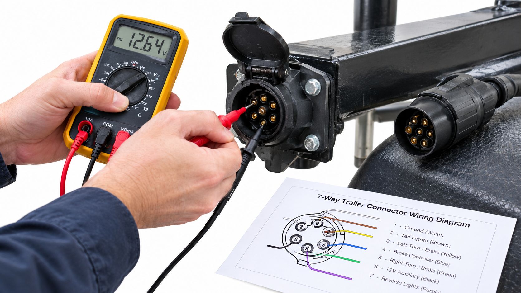
The June 1993 SAE J560 standard specifies a maximum connector-assembly voltage drop of 3 mV/A during its performance test, equivalent to approximately 0.105 V at 35 A and 0.210 V at 70 A (SAE J560 connector performance requirements). Those values are test-condition benchmarks, not a universal roadside pass/fail band for an entire trailer harness.
Measure across each suspect segment
With the affected circuit operating and the trailer connected, the technician establishes source voltage, then compares the supply at the trailer junction box and component. Measuring across a connection under load reveals resistance that an unloaded voltage or continuity check may miss.
- At the tractor socket: Confirm the commanded output and investigate source-side protection if it's absent.
- Across the pigtail: Look for loss through plug contacts, receptacle contacts, and flexing conductors.
- At the nose box: Inspect terminal condition, cable entries, and the conductor immediately behind the connection.
- Toward the lamp: Divide the harness into accessible sections instead of opening every splice.
- On the return path: Measure ground-side drop separately so a poor return isn't mistaken for missing positive power.
Oxidized contacts, loose terminal tension, water intrusion, conductor damage, and deteriorated grounds are candidates for inspection, not automatic diagnoses. The segment showing the unexplained loss becomes the repair target.
The accompanying video provides a visual reference alongside the written test sequence.
Moving the connector while monitoring the loaded circuit can help reproduce an intermittent fault, provided the vehicle is secure and access is safe. A voltage change identifies an affected area; inspection still has to establish whether the actual problem is a contact, crimp, conductor, or ground.
Intermittent Trailer ABS and the Hard Middle Case
A trailer ABS lamp that clears when the connector moves presents a different problem from a consistently dark marker lamp. A lamp that appears only during brake application also warrants investigation of the power supply. Neither symptom, by itself, identifies a wheel-speed sensor or controller failure.
Federal commercial-vehicle inspection guidance describes the expected brief ABS lamp self-test followed by extinguishing; failure to illuminate or continued illumination requires fault or compliance attention. Operational follow-through matters too: roadside inspection reports must reach the carrier within 24 hours, and out-of-service defects must be corrected before operation resumes (commercial-vehicle ABS inspection guidance, 2013).
Interpret the lamp behavior before replacing components
| Observed behavior | Diagnostic direction | What doesn't follow automatically |
|---|---|---|
| Lamp never illuminates | Check lamp operation, supply, ground, and open circuits | The ABS controller has failed |
| Lamp responds to connector movement | Investigate terminals and nearby wiring under load | The connector alone is responsible |
| Lamp appears during brake application | Compare continuous and secondary power paths | Normal brake feel proves continuous ABS power |
| Lamp remains on with stable supply | Retrieve fault information and follow component tests | Immediate sensor or controller replacement |
The continuous ABS supply path deserves particular attention when the symptom changes with brake application. Connector corrosion, damaged ABS-power wiring, an open circuit, or a poor ground should be separated from downstream faults before expensive components are considered.
Know when a meter isn't enough
A multimeter can establish whether power and ground remain dependable at the accessible test points. It can't, on its own, resolve every wheel-speed sensor, tone-ring, or controller complaint.
- Supply unstable: Repair and verify the power path before interpreting downstream symptoms.
- Supply stable but warning persists: Use suitable diagnostic equipment and the applicable component procedure.
- Physical access unsafe: Defer wheel-end or under-trailer work until controlled access is available.
A scan-tool fault description identifies a test direction, not necessarily a failed part. Wiring to a sensor still needs evaluation, and inspection of the tone ring may require access that the shoulder doesn't provide.
Dispatch shouldn't treat an extinguished warning lamp as automatic clearance. The repair outcome, inspection status, and any unresolved restrictions must be recorded separately.
Repeat Lighting Failures Usually Have Wiring Causes
A replacement lamp that works during installation doesn't prove the original assembly was defective. When the same position fails again, the technician should investigate the shared supply, return, sealing, and harness support before repeating the purchase.
The connector condition may explain more than the lamp face.
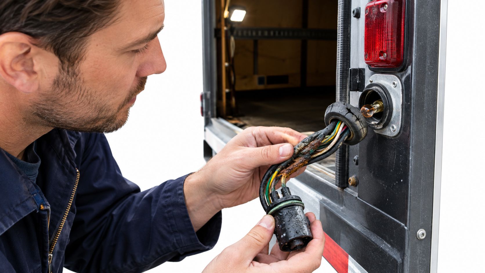
FMCSA recorded 350,886 inoperable-required-lamp violations in its 2021 statistical series and 372,664 in 2022 (FMCSA inspection profile and statistical series). These totals establish the enforcement relevance of lighting reliability; they don't establish what proportion of failures came from wiring.
Preserve the intermittent fault evidence
Moisture, road contamination, vibration, and repeated cable flexing belong in the inspection because they can affect connections and conductors. A loose junction or chafed section may behave differently while parked than during travel.
Useful evidence includes:
- Photographs before movement: Capture routing, unsupported sections, connector position, and visible damage before handling the harness.
- Loaded ground measurements: Demonstrate return-path loss rather than judging a ground fastener by appearance.
- Component-side supply findings: Separate a failed LED assembly from an upstream feed problem.
- Routing observations: Check accessible areas near suspension movement, frame edges, and rear doors.
Replacing a lamp is justified when the supply and return are sound and component testing identifies failure. Replacing it merely because it's dark leaves the upstream fault unaddressed.
Maintenance insight: A repeat failure at the same location calls for a review of the installation, not just the replacement part.
Turn repeat incidents into a maintenance pattern
The FMCSA public motor-carrier inspection dataset includes inspection and violation information that fleets can use alongside their own repair records. The practical fleet-level task is to connect repeated symptoms to the same trailer, circuit, location, and prior corrective work.
An entry that only says “light replaced” won't support that review. A record identifying water intrusion at a junction, damaged strain relief, or excessive ground-side loss gives the next technician a specific starting point without claiming that every recurrence has the same cause.
Compliance Checks That Travel With the Repair
A lamp coming on once isn't a complete repair acceptance test. The relevant question is whether the required function remains dependable in its operating conditions, with the lamp properly mounted and visible.
Federal rules require required lamps to be capable of operation at all times and powered by the motor vehicle's electrical system, subject to the projecting-load exception. They also prohibit required lamps and reflective devices from being obscured by the tailboard, load, covering, dirt, or added equipment (49 CFR Part 393, current regulatory text).
Restore electrical and physical protection
FMCSA guidance addresses stop-lamp activation, secure mounting and visibility, wiring enclosure, and trailer circuit overload protection that may be supplied by the towing vehicle (FMCSA lighting and wiring compliance guidance, undated guidance). Repair quality therefore includes more than restoring a conductive path.
Corrective work should address the defect found:
- Contact damage: Clean serviceable contacts or replace heat-damaged terminals, preserving proper engagement.
- Splice exposure: Use an appropriate sealed repair and restore the wiring's physical protection.
- Harness movement: Secure routing away from sharp edges and suspension travel.
- Ground deterioration: Restore a sound connection rather than leaving corrosion beneath the fastener.
A jumper that holds the circuit on but defeats protection or leaves exposed wiring isn't an acceptable substitute for a completed repair.
Verify functions under realistic conditions
The technician should test affected tail, marker, turn, stop, and applicable ABS-power functions independently, then check relevant simultaneous operation. A controlled tug and movement check of the jumper can reveal a connection that passed only while undisturbed.
Source voltage, load-side voltage, and the repaired location belong in the maintenance file. The record should also identify any condition that couldn't be reproduced or verified.
The same discipline supports recognizing commercial-truck DOT inspection warning signs before a route. Electrical verification doesn't excuse an obscured lamp, unsecured mounting, or another unresolved inspection concern.
Where the Repair Happens and What to Document
Mobile service describes where technicians attend, not a promise that every repair is feasible there. A protected vehicle location may support connector, ground, or accessible harness work. Extensive damage or unsafe access can change that decision.
The Road Services model has no customer-facing workshop. If controlled repair conditions are necessary, the option is a suitable external facility, not a customer drop-off at a company repair bay.
Decide whether the location supports the job
Feasibility depends on the actual vehicle position and repair scope:
- Ground and traffic clearance: The vehicle must be secure, with safe working space away from live traffic.
- Access: Nose-box testing may be accessible even when under-trailer work isn't.
- Equipment: The required testing and repair equipment must be available for the specific fault.
- Damage extent: Localized wiring damage differs from replacement requiring broad harness access.
- Related defects: Brake, air, suspension, or structural damage may affect whether electrical work can safely proceed.
Any arrival estimate remains conditional on location, traffic, technician availability, and the job. Dispatch should communicate those conditions rather than treat a response target as a guaranteed arrival.
Keep a usable handoff record
NHTSA-hosted 2022 service documentation illustrates checking both vehicle-side and trailer-side connectors, operating the lamps, and investigating relevant fuses when circuits fail (trailer-light diagnostic service procedure). It's an example of diagnostic logic, not a universal semi-trailer fuse chart.
The carrier's record should identify the failed function, remaining working functions, connector condition, fuse status, voltage findings, and photographs of harness or ground damage. It should distinguish confirmed findings from suspected causes.
The fleet breakdown response checklist before requesting mobile truck repair supports gathering that information before dispatch. A clear handoff helps an attending technician or external facility continue testing without assuming that an unverified diagnosis is established fact.
Putting the Method to Work on the Road
In the hypothetical marker-lamp incident, connector movement provides a lead, not a conclusion. Testing must determine whether the loss occurs at the tractor output, through the pigtail, inside the nose box, along the harness, or at the return connection. Only then can the technician justify a terminal repair, wiring repair, or component replacement.
The unresolved ABS warning requires its own assessment. Restoring the marker lamp doesn't establish that the continuous ABS supply is reliable or that a downstream fault has cleared.
Make the dispatch decision from the findings
A useful debrief gives the carrier concrete answers:
- Fault located: Identify the tested segment and evidence supporting the diagnosis.
- Repair scope established: State what can safely be corrected at the present location.
- Verification recorded: Identify completed function checks and anything unresolved.
- Operating restrictions addressed: Separate the technical repair outcome from inspection or out-of-service requirements.
Semi trailer electrical repair is a power-path decision before it's a parts decision. That approach gives operators a better basis for controlling unnecessary replacement, repeat downtime, and compliance exposure without promising a particular cost or roadside outcome.
SAAT Repairs Corp offers mobile commercial semi-trailer electrical diagnostics and repair across Tampa, Lakeland, and nearby Florida corridors, subject to safe access and job feasibility. Drivers and dispatchers can visit SAAT Repairs Corp and use the English contact section to provide the vehicle location, failed functions, and available photographs for a case-by-case mobile assessment.